Elegoo

⌘K
  1. Home
  2. /
  3. Docs
  4. /
  5. Elegoo
  6. /
  7. Elegoo Orangestorm Giga
  8. /
  9. OrangeStorm Giga – ...

OrangeStorm Giga – Sostituzione della Scheda della Testa di Stampa

Strumenti e materiali

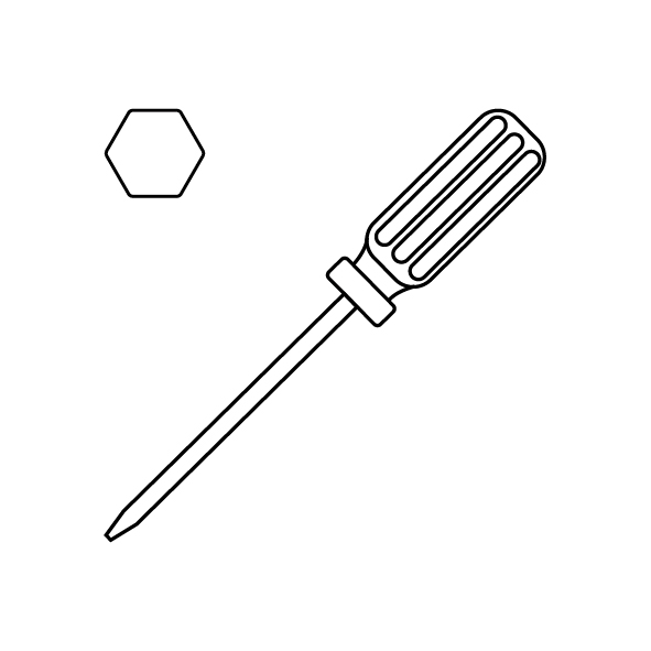
  • Una chiave a brugola da 2,0 mm
  • Una nuova Adapter Board
1.png

Tutorial Video

Istruzione

  1. Spegni la stampante e stacca il cavo di alimentazione.
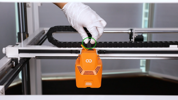
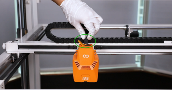
  2. Scollega i cavi a nastro sopra la testina di stampa.
    image1.png
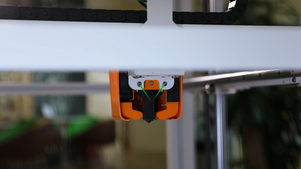
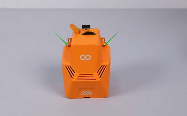
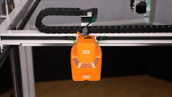
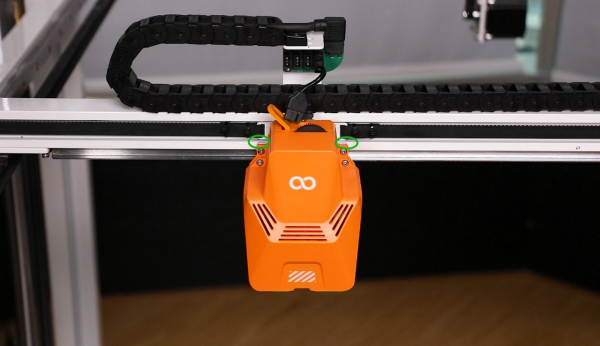
  3. Allenta le 2 viti che fissano la parte posteriore della testina di stampa usando una chiave a quattro torni da 2,0 mm.
    image2.png
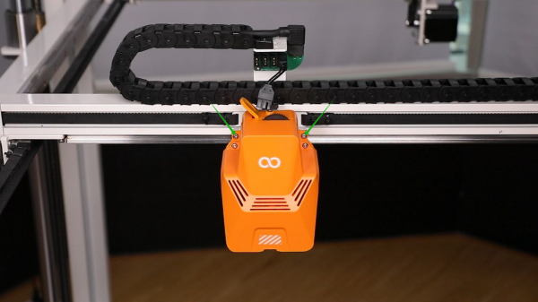
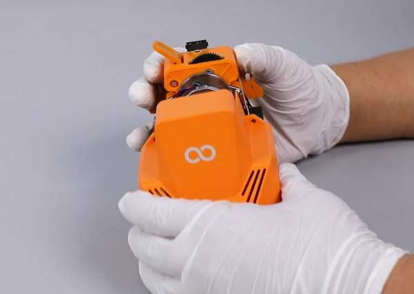
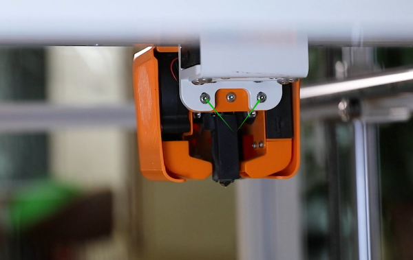
  4. Allenta le 2 viti che fissano la parte anteriore della testina di stampa usando una chiave a quattro quattro zampe da 2,0 mm e rimuovi la testina di stampa.
    Nota: Tieni la testina di stampa allentando l’ultima vite per evitare che cada.
    image3.png
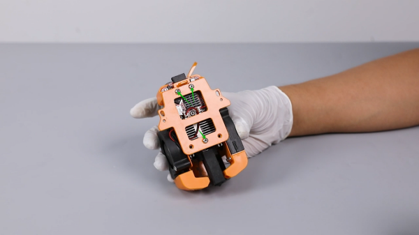
  5. Loosen the 2 screws securing the front cover of the print head using a 2.0 mm Allen wrench and remove the front cover.
    image4.png
    image5.png
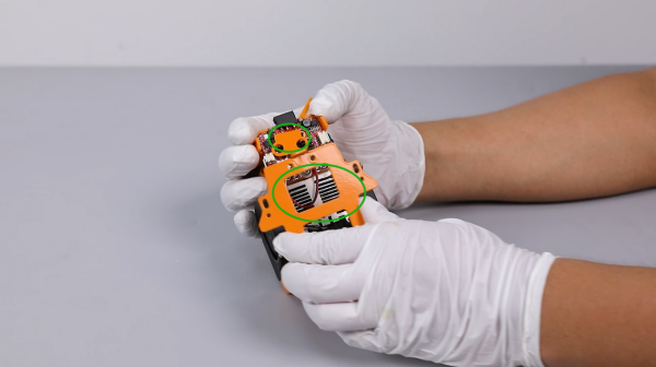
  6. Loosen the 3 screws securing the back plate of the printing head using a 2.0 mm Allen wrench and remove the back plate and pressing plate of the adapter board.
    image6.png
    image7.png
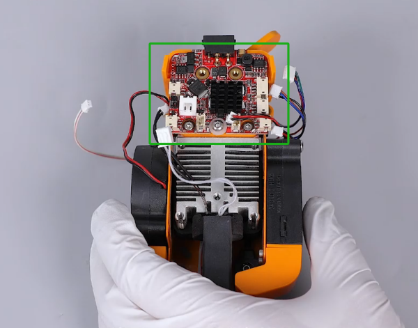
  7. Unplug all ribbon cables from the ports on the adapter board of the printing head.
    image8.png
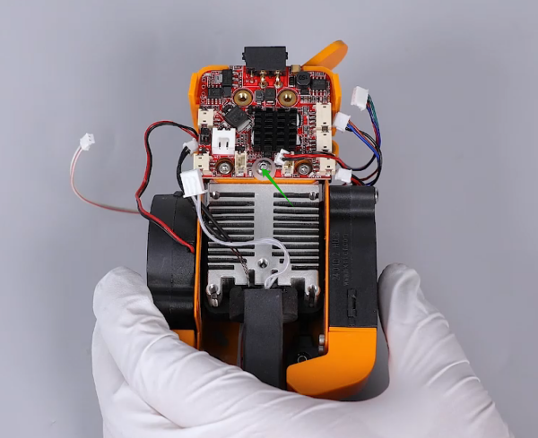
  8. Loosen the screw securing the adapter board of the printing head using a 2.0 mm Allen wrench and remove the old adapter board of the printing head.
    image9.png
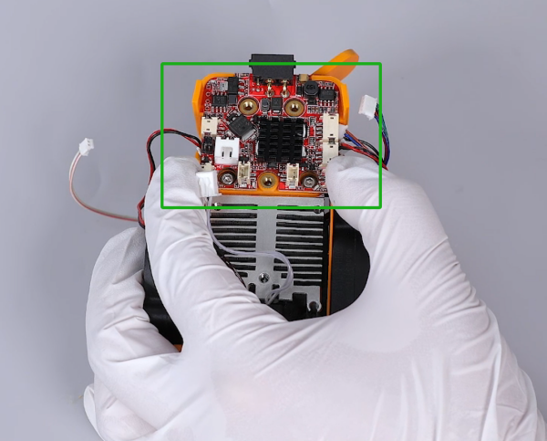
  9. Prepare the new adapter board of the printing head. Put it in the installation position by aligning it with the screw holes.
    image10.png
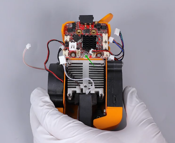
  10. Put the gasket in the installation position by aligning it with the screw holes. Tighten the screws securing the adapter board of the printing head using a 2.0 mm Allen wrench.
    image11.png
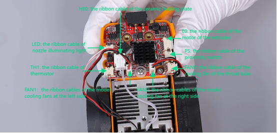
  11. Insert the ribbon cables to the adapter board of the printing head according to their functions and the shape of the ports.
    image12.png
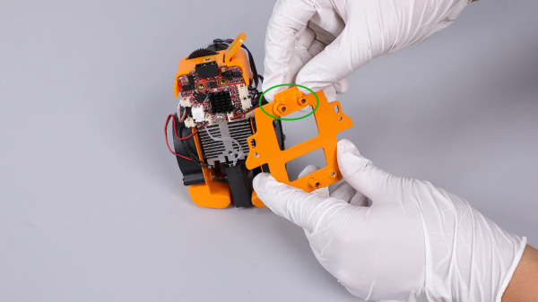
  12. Prepare the the back plate of the printing head and the pressing plate of the adapter board. Attach the pressing plate onto the screw holes on the back plate.
    Note: The pressing plate has its fixed installation direction.
    image13.png
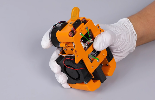
  13. Put the back plate assembly of the printing head in the installation position by aligning it with the screw holes. Tighten the 3 securing screws using a 2.0 mm Allen wrench.
    image14.png
  14. Put the front cover in the installation position by aligning it with the screw holes, and tighten the 2 securing screws using a 2.0 mm Allen wrench.
    image15.png
  15. Put the entire printing head in the installation position by aligning it with the screw holes, and tighten the 2 securing screws using a 2.0 mm Allen wrench.
    image16.png
  16. Note: Align the level of the the screw holes above the back plate’s two sides with the top of the mounting bracket of the printing head.
    image17.png
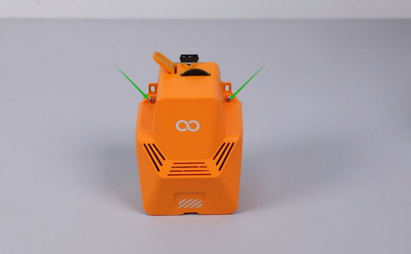
  17. Tighten the 2 screws securing the rear of the printing head using a 2.0 mm Allen wrench.
    image18.png
  18. Insert the ribbon cables above the printing head.
    image19.png
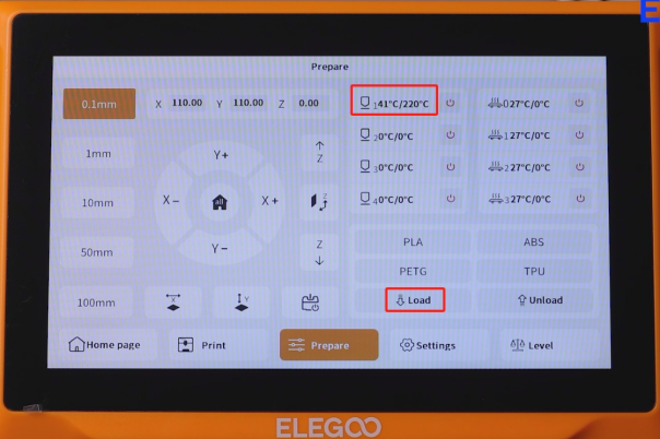
  19. Power on the printer. Touch “Prepare” and set the nozzle temperature to 220 °C. After the temperature reaches to the set temperature, touch “Load” on the touchscreen.
    image20.png
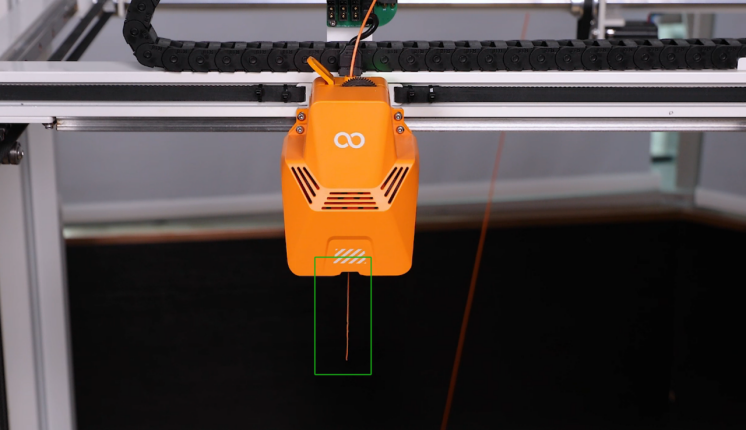
  20. La stampante può essere usata normalmente dopo che il filamento è stato estruso normalmente e la stampante è stata rilivellata.
    image21.png