* Si prega di leggere l’intero manuale prima di utilizzare la stampante.
AVVERTIMENTO
Questo è un prodotto di classe A. In un ambiente domestico, questo prodotto può causare interferenze radio, nel qual caso all’utente potrebbe essere richiesto di adottare misure adeguate.
Dichiarazione di responsabilità
Le informazioni contenute in questo manuale sono soggette a modifiche senza preavviso. Shanghai Fusion Tech Co. Ltd. (qui indicata anche come “Raise3D”) non è responsabile per errori in questo manuale. Raise3D non si assume alcuna responsabilità per perdite accidentali o secondarie causate dalla fornitura, dalle prestazioni o dall’uso di questo manuale. Raise3D non fornisce alcuna garanzia per questo manuale, incluse, a titolo esemplificativo ma non esaustivo, le garanzie implicite di commerciabilità e idoneità per scopi specifici. Il proprietario del sistema/acquirente del materiale è responsabile di determinare se il materiale Raise3D è sicuro, legale e tecnicamente adatto all’applicazione prevista e, allo stesso tempo, di determinare il metodo di smaltimento (o riciclaggio) appropriato in conformità con le normative ambientali locali. A meno che non siano stipulate le condizioni di vendita standard di Raise3D, Raise3D non sarà responsabile per eventuali perdite causate dall’uso dei prodotti descritti in questo manuale. Il proprietario del sistema/acquirente del materiale è responsabile di determinare se i materiali utilizzati soddisfano i requisiti di Raise3D, altrimenti Raise3D non sarà responsabile per eventuali perdite causate dall’uso dei prodotti descritti in questo manuale.
Dichiarazione di copyright
Il presente documento è protetto da copyright e tutti i diritti sono riservati. L’uso, la divulgazione e il possesso di questo documento sono limitati dal copyright del software e dall’accordo stabilito da Raise3D. Nulla di quanto contenuto in questo documento può essere fotocopiato, riprodotto o tradotto in un’altra lingua, a meno che non si ottenga la preventiva autorizzazione scritta di Shanghai Fusion Tech Co. Ltd.
Tutti i disegni e le informazioni contenute in questo manuale sono di proprietà di Shanghai Fusion Tech Co. Ltd. È vietato qualsiasi uso e copia non autorizzati.
Dichiarazione di proprietà del marchio
Raise3D e ideaMaker sono marchi registrati di Shanghai Fusion Tech Co. Ltd.
WINDOWS è un marchio registrato di Microsoft Corporation.
macOS è un marchio registrato di Apple Inc.
Tutti gli altri nomi di prodotti e marchi sono di proprietà dei rispettivi proprietari e Raise3D non è responsabile per la selezione, le prestazioni o l’uso di questi prodotti non Raise3D. Le specifiche del prodotto sono soggette a modifiche senza preavviso.
Misure di sicurezza
Si prega di leggere le informazioni sulla sicurezza per assicurarsi di utilizzare l’apparecchio in sicurezza.
Generalità
Le informazioni generali su questo manuale di istruzioni sono disponibili qui.
§ Leggere attentamente questo manuale di istruzioni. Solo questo ti garantirà un utilizzo sicuro ed efficiente dell’apparecchio.
§ Questo manuale è destinato all’installatore e all’utente dell’apparecchio.
§ Seguire le istruzioni e le avvertenze di sicurezza.
§ Conservare il manuale di istruzioni e le informazioni sul prodotto al sicuro per riferimenti futuri o per il prossimo proprietario.
§ Controllare l’apparecchio dopo averlo disimballato. Non collegare l’apparecchio se è stato danneggiato durante il trasporto.
§ In caso di domande, contattare il nostro centro di assistenza locale o i distributori.
§ Eventuali guasti e perdite causati dall’ignoranza dei seguenti elementi menzionati e delle precauzioni menzionate nelle istruzioni per l’uso e l’installazione non sono coperti dalla nostra garanzia e da qualsiasi responsabilità.
Destinazione d’uso
Leggere le informazioni sull’uso previsto per assicurarsi di utilizzare l’apparecchio in modo corretto e sicuro.
Utilizzare solo questo apparecchio:
§ Secondo questo manuale di installazione e istruzioni;
§ In un ambiente ben ventilato e asciutto;
§ Le condizioni ambientali utilizzate sono:
Temperatura ambiente di esercizio: 15-30°C, 10-90% RH senza condensa
Temperatura di stoccaggio: da -25 °C a +55 °C, 10-90% di umidità relativa senza condensa
Limitazione del gruppo di utenti
§ Tenere i bambini, gli animali domestici e le persone vulnerabili lontani dall’apparecchio.
§ Questa apparecchiatura non è adatta per l’uso in luoghi in cui è probabile la presenza di bambini.
§ Questa attrezzatura può essere utilizzata solo da personale qualificato. Questo apparecchio può essere utilizzato da persone che hanno ridotte capacità fisiche, sensoriali o mentali o esperienza e/o conoscenza inadeguate, a condizione che siano sorvegliate o siano state istruite su come utilizzare l’apparecchio in sicurezza e abbiano compreso i pericoli che ne derivano.
Installazione sicura
Prendere nota delle istruzioni di sicurezza durante l’installazione dell’apparecchio.
ATTENZIONE – Rischio di scossa elettrica!
§ Un’installazione impropria è pericolosa.
Collegare e utilizzare l’apparecchio solo in conformità con le specifiche sulla targhetta matricola.
Collegare l’apparecchio ad una rete elettrica con corrente alternata solo tramite una presa con messa a terra correttamente installata.
Il sistema di conduttori di protezione dell’impianto elettrico domestico deve essere installato correttamente. L’installazione deve avere una sezione trasversale sufficientemente grande.
Assicurarsi che il sistema di alimentazione (corrente, tensione e cavi) sia in grado di soddisfare i normali requisiti di carico degli apparecchi elettrici.
Non dotare mai l’apparecchio di un dispositivo di commutazione esterno, ad es. timer o telecomando.
Durante l’installazione dell’apparecchio, verificare che il cavo di alimentazione non sia intrappolato o danneggiato.
Selezionare il fusibile in base ai requisiti di identificazione di sicurezza del fusibile.
La spina di alimentazione e la presa devono corrispondere e la lama di messa a terra deve funzionare correttamente e il corpo deve essere adeguatamente messo a terra.

§ Se l’isolamento del cavo di alimentazione è danneggiato, ciò è pericoloso.
Non lasciare mai che il cavo di alimentazione entri in contatto con parti calde dell’apparecchio o fonti di calore.
Non lasciare mai che il cavo di alimentazione entri in contatto con punte o spigoli vivi.
Non piegare, schiacciare o modificare mai il cavo di alimentazione.
§ Quando la macchina è collegata, toccare il guscio della macchina e scoprire che c’è induttanza elettrostatica. Ciò indica che la macchina in casa non è ben collegata a terra. Scollegare la macchina e riparare immediatamente il collegamento di alimentazione per garantire una buona messa a terra.
§ Non collegare l’alimentatore con le mani bagnate.
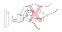
§ In caso di domande, consultare un elettricista professionista.
ATTENZIONE – Rischio di incendio!
§ È pericoloso utilizzare un cavo di alimentazione prolungato e adattatori non approvati.
Non utilizzare prolunghe o prese multiple.
Se il cavo di alimentazione è troppo corto, contattare il Servizio Clienti.
Utilizzare solo adattatori approvati dal produttore.
§ Se l’isolamento del cavo di alimentazione è danneggiato, è molto pericoloso.
AVVERTENZA – Pericolo di lesioni!
§ Il peso elevato dell’apparecchio può causare lesioni durante il sollevamento.
Non sollevare l’apparecchio da soli.
ATTENZIONE – Rischio di soffocamento!
§ I bambini possono mettere del materiale di imballaggio sopra la testa o avvolgersi in esso e soffocare.
Tenere il materiale di imballaggio lontano dalla portata dei bambini.
Non lasciare che i bambini giochino con il materiale di imballaggio.
AVVERTENZA – Pericolo di lesioni!
§ L’apparecchio può vibrare durante l’uso.
Posizionare l’apparecchio su una superficie pulita, piana e solida.
§ Se i tubi e i cavi di alimentazione sono stati posati in modo errato, ciò può causare un rischio di inciampo.
Posare i tubi e i cavi di alimentazione in modo tale da non rischiare di inciampare.
§ Se l’apparecchio viene spostato tenendolo per i componenti sporgenti, come la porta dell’apparecchio, le parti potrebbero rompersi.
Non spostare il dispositivo tenendolo per le parti sporgenti.
AVVERTENZA – Rischio di taglio!
§ Il contatto con gli spigoli vivi dell’apparecchio può causare tagli.
Non toccare gli spigoli vivi dell’apparecchio.
Indossare guanti protettivi durante l’installazione e il trasporto dell’apparecchio.
Uso sicuro
Seguire queste istruzioni di sicurezza quando si utilizza l’apparecchio.
ATTENZIONE – Rischio di scossa elettrica!
§ Se l’apparecchio o il cavo di alimentazione sono danneggiati, ciò è pericoloso.
Non utilizzare mai un apparecchio danneggiato.
Non tirare mai il cavo di alimentazione per scollegare l’apparecchio. Scollegare sempre l’apparecchio dalla presa di corrente.
Se l’apparecchio o il cavo di alimentazione sono danneggiati, scollegare immediatamente il cavo di alimentazione.
Chiama il servizio clienti, fai riferimento al capitolo Difficoltà riscontrate/Informazioni di contatto.
Le riparazioni dell’apparecchio devono essere eseguite solo da personale specializzato addestrato.
§ L’ingresso di umidità può causare una scossa elettrica.
Non esporre mai l’apparecchio a calore o umidità intensi.
Non utilizzare pulitori a vapore o spray per pulire l’apparecchio.
AVVERTENZA – Rischio di danni alla salute!
§ I bambini possono chiudersi all’interno dell’apparecchio, mettendo così a rischio la loro vita.
Non installare l’apparecchio dietro una porta in quanto ciò potrebbe ostruire la porta dell’apparecchio o impedirne l’apertura.
Con gli apparecchi ridondanti, scollegare il cavo di alimentazione e tagliare il cavo.
ATTENZIONE – Rischio di soffocamento!
§ I bambini possono inalare o ingerire piccole parti, provocandone il soffocamento.
Tenere le piccole parti lontano dalla portata dei bambini.
Non lasciare che i bambini giochino con piccole parti.
ATTENZIONE – Pericolo di lesioni!
§ il piano di copertura potrebbe rompersi se si sale o ci si arrampica sull’apparecchio.
Non salire o salire sull’apparecchio.
§L’apparecchio potrebbe ribaltarsi se ci si siede o ci si appoggia alla porta aperta.
Non sedersi o appoggiarsi alla porta dell’apparecchio.
Non appoggiare alcun oggetto sulla porta dell’apparecchio.
§ Raggiungere la camera mentre il sistema a tre assi è ancora in movimento può causare lesioni alle mani.
Attendere che il sistema a tre assi si fermi completamente prima di raggiungere l’interno.
§ La spatola fornita nella confezione degli accessori ha le parti affilate. Se la spatola viene utilizzata in modo improprio, l’utente potrebbe ferirsi.
Non toccare il bordo della spatola.
Tenere i bambini lontani dalla spatola.
§ Alcune parti della stampante sono affilate e possono causare lesioni.
§ Quando si rimuove il modello di stampa, fare riferimento al capitolo Rimozione del modello stampato.
ATTENZIONE – Rischio di ustioni!
§ Durante il funzionamento o la stampa ad alte temperature, il guscio dell’apparecchio si surriscalda.
Non toccare il piano di stampa quando la stampante si sta riscaldando.
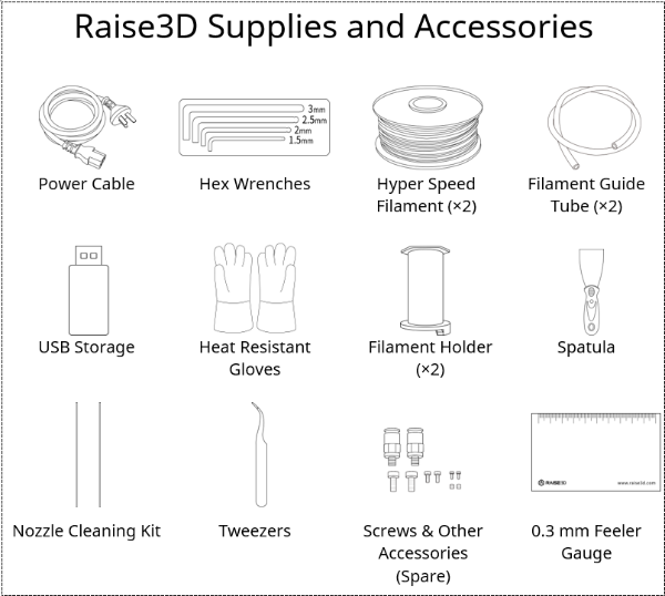
Si prega di indossare i guanti termoisolanti forniti nella scatola degli accessori per il funzionamento.
Si prega di tenere i bambini lontani dal piano di stampa riscaldata.
§ La temperatura dell’estrusore è molto alta durante la stampa.
Si prega di non toccare l’estrusore quando si sta riscaldando.
Si prega di indossare i guanti termoisolanti forniti nella scatola degli accessori per il funzionamento.
Si prega di tenere i bambini lontani dall’estrusore riscaldato.
Manutenzione sicura
Osservare le istruzioni di sicurezza durante l’esecuzione di lavori di manutenzione sull’apparecchio.
ATTENZIONE – Rischio di scossa elettrica!
§ Le riparazioni improprie sono pericolose.
Le riparazioni dell’apparecchio devono essere eseguite solo da personale specializzato addestrato.
Per la riparazione dell’apparecchio utilizzare solo pezzi di ricambio e accessori originali del produttore.
Se il cavo di alimentazione di questo apparecchio è danneggiato, deve essere sostituito dal produttore, dal servizio clienti del produttore o da una persona similmente qualificata al fine di prevenire qualsiasi rischio.
§ L’ingresso di umidità può causare una scossa elettrica.
Non utilizzare pulitori a vapore o spray per pulire l’apparecchio.
AVVERTENZA – Pericolo di lesioni!
§ L’uso di ricambi e accessori non originali è pericoloso.
Utilizzare solo pezzi di ricambio e accessori originali del produttore.
Segnaletica di sicurezza
Superficie calda: Il segno della superficie calda indica la presenza di dispositivi con temperature elevate. Prestare sempre la massima attenzione quando si lavora intorno a componenti riscaldati.
Attendere mezz’ora dopo aver spento la stampante prima di maneggiare le parti per evitare ustioni.

Moving Parts: Do not put fingers, clothing or hair into gears and other hazardous parts to avoid electric shock, injury, fire, or damage to the device.

High Voltage: The high voltage sign indicates the presence of high voltages. Always stay away from exposed circuitry. It is recommended that all conductors be removed.

Replacement Fuse Identification and Rating Markings: Identification of a suitable replacement fuse shall be marked adjacent to the fuse holder.

Protective Earthing Conductor Terminal: Marked near the protective earthing conductor terminal.

A. Declarations and Safety Statements
FCC Statement
Please take attention that changes or modification not expressly approved by the party responsible for compliance could void the user’s authority to operate the equipment.
This device complies with Part 15 of the FCC Rules. Operation is subject to the following two conditions:
(1) This device may not cause harmful interference, and
(2) This device must accept any interference received, including interference that may cause undesired operation.
This equipment complies with FCC radiation exposure limits set forth for an uncontrolled environment. This equipment should be installed and operated with minimum distance 20cm between the radiator & your body.
EU Conformity Statement
 | This product and-if applicable-the supplied accessories too are marked with “CE” and comply therefore with the applicable harmonized European standards listed under the RE Directive 2014/53/EU, the EMC Directive 2014/30/EU, LVD Directive 2014/35/EU, the RoHS Directive 2011/65/EU. |
 | 2012/19/EU (WEEE directive): Products marked with this symbol cannot be disposed of as unsorted municipal waste in the European Union. For proper recycling, return this product to your local supplier upon the purchase of equivalent new equipment, or dispose of it at designated collection points. For more information see: http:// www.recyclethis.info. |
 | 2006/66/EC (battery directive): This product contains a battery that cannot be disposed of as unsorted municipal waste in the European Union. See the product documentation for specific battery information. The battery is marked with this symbol, which may include lettering to indicate cadmium (Cd), lead (Pb), or mercury (Hg). For proper recycling, return the battery to your supplier or to a designated collection point. For more information see: www.recyclethis.info. |
UKCA Conformity Statement
 | This product is marked with “UKCA” and in conformity with the relevant UK statutory requirement: Radio Equipment Regulations 2017. Full text of the UK declaration of conformity is available at https://www.raise3d.com. |
| UK sales partner company name:3DGBIRE LtdUK sales partner company address: 3DGBIRE, Unit 44/45 Chorley North Industrial Estate, Drumhead Road, Chorley, Lancashire, PR67BX | |
Electromagnetic Compatibility – EMC
Simplified EU Declaration of Conformity
Raise3D declares that this device is in compliance with the essential requirements and
other relevant provisions of Directive 2014/53/EU. Full text of the EU declaration of
conformity is available at https://www.raise3d.com.
RF Exposure Information
This device has been tested and meets applicable limits for Radio Frequency (RF) exposure.
This equipment must be installed and operated in accordance with provided instructions and the antenna(s) used for this transmitter must be installed to provide a clearance of at least 20 cm from all persons and must be co-located or operating in conjunction with any other antenna or transmitter.
CE&UKCA Mark Warning
The device is restricted to indoor use only when operating in the 5150 to 5250 MHz frequency range.
 |  | ||||||
 | BE | EE | HR | IT | CY | LV | LT |
| BG | IE | LU | HU | MT | NL | AT | |
| CZ | EL | PL | PT | RO | SI | SK | |
| DK | ES | FI | SE | DE | FR | LI | |
| NO | IS | CH | TR | UK(NI) | UK | ||
CE&UKCA Output Power Table:
| Function | Frequency | Frequency |
| Wi-Fi | 2412-2472 MHz | 18 dBm(b)/ 18 dBm(g)/ 13dBm(HT) |
| 5150-5250 MHz | 19 dBm(a)/ 18.5 dBm(HT20)/ 17.5 dBm(HT40) | |
| 5725-5850 MHz | 14 dBm(a)/ 14 dBm(HT20)/ 14 dBm(HT40) |
FCC Output Power Table:
| Function | Frequency | Frequency |
| Wi-Fi | 2412-2462 MHz | 18.31 dBm(b)/ 15.62 dBm(g)/ 14.9dBm(HT) |
| 5150-5250 MHz | 15.36 dBm(a)/ 14.79 dBm(HT20)/ 14.41 dBm(HT40) | |
| 5725-5850 MHz | 15.48 dBm(a)/ 14.49 dBm(HT20)/ 14.06dBm(HT40) |
Installation
To facilitate operation and maintenance, maintain a proper distance of 50 cm on the side of the printer, 80 cm on the front, 20 cm on the back, and 60 cm on the top during installation. No flammable materials are allowed around the installation location.
Note: During low-temperature transportation, the printer may encounter frost or icing hazards. The printer can be stored at room temperature for 4-6 hours before operating.
Filament and Electrical Precautions
It is strongly recommended to use Raise3D official filaments and/or default settings for better performance. The Raise3D printer is designed to be highly compatible with Raise3D official filaments. Be extremely careful when printing with unverified filaments and settings to prevent abnormal printing results or damaging the printer.
Warning: The printer belongs to EN55032 Class A. In a residential environment, the printer may cause radio interference.
Odor
The printer emits a thermoplastic smell when in operation.
Note: Place the printer in a well-ventilated and dry environment.
Oil in the air accumulating inside the printer may damage plastic parts. Air in a cavity with excessive solid particles (conductive or non-conductive) may cause damage to the printer.
B. Technical Specifications
| Printer | Raise3D Pro3 HS | Raise3D Pro3 Plus HS | |||
| Build Volume(W×D×H) | Single Extruder Print | Dual Extruder Print | Single Extruder Print | Dual Extruder Print | |
| 300×300×300 mm(11.8 × 11.8 × 11.8 inch) | 255×300×300 mm(10 × 11.8 × 11.8 inch) | 300×300×605 mm(11.8 × 11.8 × 23.8 inch) | 255×300×605 mm(10 × 11.8 × 23.8 inch) | ||
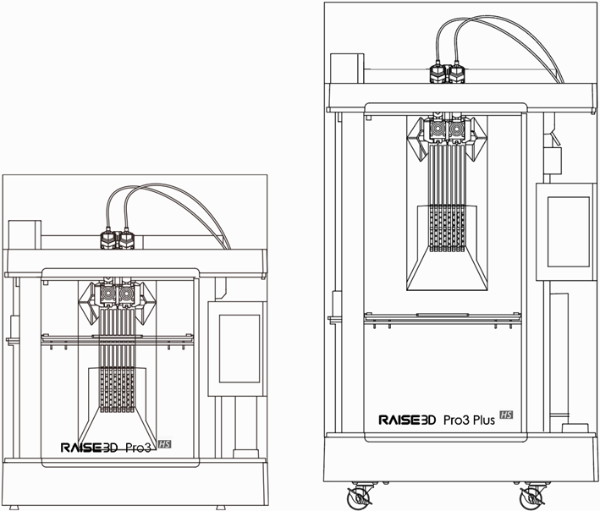
| Machine Size(W×D×H) | 620×626×760 mm(24.4 × 24.6 × 29.9 inch) | 620×626×1105 mm(24.4 × 24.6 × 43.5 inch) | |||
| Weight | Net Weight | Gross Weight (Carton with Pallet) | Net Weight | Gross Weight (Carton with Pallet) | |
| 54 kg (119 lbs) | 75.7 kg (166.9 lbs) | 64 kg (141 lbs) | 88.7 kg (195.5 lbs) | ||
| General | Print Technology | Fused Filament Fabrication (FFF) | |||
| Print Head System | Dual-head with Electronic Lifting System | ||||
| Filament Diameter | 1.75 mm | ||||
| XYZ Step Size | 0.78125, 0.78125, 0.078125 micron | ||||
| Standard Printing Speed | 300 mm/s | ||||
| Build Plate | Flexible Steel Plate with BuildTak | ||||
| Build Plate Leveling | Mesh-leveling with Flatness Detection | ||||
| Heated Bed Material | Silicone | ||||
| Heated Bed Max Temperature | 120°C | ||||
| Nozzle Diameter | 0.4 mm (Default), 0.2/ 0.6/ 0.8/ 1.0 mm (Available) | ||||
| Max Nozzle Temperature | 320°C | ||||
| Layer Height | The Pro3 HS Series is compatible with 0.2, 0.4, 0.6, 0.8 and 1.0 mm nozzles, and the layer height can vary between 0.05-0.6 mm. To achieve stable print results, when using 0.4 mm nozzles, we recommend using a layer height between 0.1-0.3 mm. | ||||
| Automatic Filament Switching | Available (Coming Soon) | ||||
| RFID Sensor | Available (Coming Soon) | ||||
| Filament Run-Out Sensor | Available | ||||
| Filter | HEPA Filter with Activated Charcoal | ||||
| EVE Smart Assistant | Available | ||||
| Connectivity | Wi-Fi, LAN, USB port, Live Camera | ||||
| Noise Emission | < 55 dB (A) When Building | ||||
| Operating Ambient | 15-30°C, 10-90% RH, non-condensing | ||||
| Storage Temperature | -25°C to +55°C, 10-90% RH, non-condensing | ||||
| Electrical | Power Supply Input | 100-240 VAC, 50/60 Hz 230 V @ 3.3 A | |||
| Power Supply Output | 24 V DC, 600 W | ||||
| Material | Material Type | Hyper Core: PPA CF/ PPA GF/ ABS CFHyper Speed: PLA/ ABSIndustrial: PPA CF/ PPA GF/ PET CF/ PET GF/ PETG ESD/ PET Support/ PPA SupportPremium: PLA/ ABS/ ASA/ PETG/ PC/ TPU-95A/ PVA+ | |||
| Third Party Material | Supported by Raise3D OFP (Open Filament Program)* | ||||
| Software | Slicing Software | ideaMaker | |||
| Supported File Types | STL/ OBJ/ 3MF/ OLTP/ STEP/ STP/ IGES/ IGS | ||||
| Supported OS | Windows/ macOS/ Linux | ||||
| Machine Code Type | GCODE | ||||
| Printer Controller | User Interface | 7-inch Touch Screen | |||
| Network | Wi-Fi, Ethernet | ||||
| Power Loss Recovery | Available | ||||
| Screen Resolution | 1024×600 | ||||
| Motion Controller | Atmel ARM Cortex-M4 120MHz FPU | ||||
| Logic Controller | NXP ARM Cortex-A9 Quad 1GHz | ||||
| Memory | 1 GB | ||||
| Onboard Flash | 16 GB | ||||
| OS | Embedded Linux | ||||
| Ports | USB 2.0×2, Ethernet×1 | ||||
*For detailed information and slicing profiles of the materials supported by Raise3D OFP, please visit https://www.ideamaker.io/.
C. Main Parts
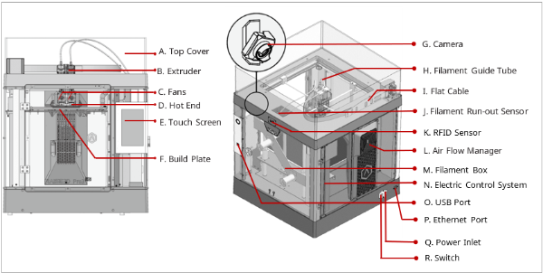
Pro3 HS
Pro3 Plus HS
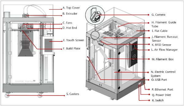
A. Top Cover
The upper cover of the printer.
B. Extruder
The part extruding filament to the hot end. Brand-new unitized extruders, which are more convenient for assembly and dismounting. The printer’s dual extrusion structure can adapt to a variety of filaments.
C. Fans
The part used to cool the heat down.
D. Hot End
The part that melts filaments. With a quick-release design, even beginners can quickly remove the hot end within one minute, making it more convenient to repair the hot end after removing it.
E. Touch Screen
The part that you can control the printer and check the printer status.
F. Build Plate
A plate for printing the model.
G. Camera
The part used to observe the operation of the printer.
H. Filament Guide Tube
The part that protects and guides filaments.
I. Flat Cable
The integrated cable that transmits the signal from the motion controller board to the extruder. The latest flat cable iteration reduces drag on the printhead and avoids the sagging of the cross shaft.
J. Filament Run-out Sensor
An automated optical detection system is adopted to detect whether the filaments are sufficient. When the filaments are running out, the printer will automatically stop printing.
K. RFID Sensor
Uses RFID tags and readers for information transmission and identification between the printer and filaments.
L. Air Flow Manager
An air filter manager including a fan and a HEPA filter, which is used to enhance air circulation inside the printer.
M. Filament Box
The place where the filament is discharged, which can accommodate 2 spools of 1kg filaments at the same time.
N. Electric Control System
It stores the motion controller board.
O. USB Interface
Two USB2.0 interfaces.
P. Ethernet Port
RJ45 is connected to the port to connect your printer to a network.
Note: The length of the network cable should not exceed 3 m.
Q. Power Inlet
The place to connect power cable.
R. Switch
The power switch to turn on/off the printer.
S. Casters
Four swiveling and double-locking casters.
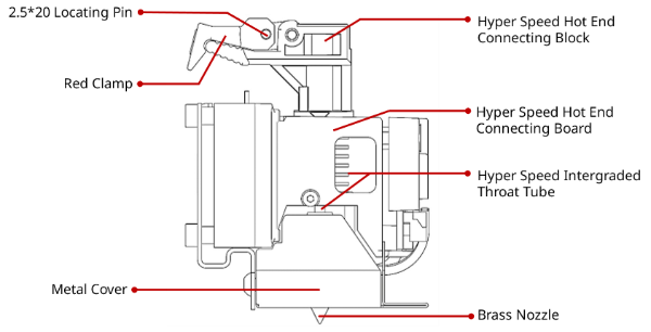
Hyper Speed Hot End
D. Hardware Installation
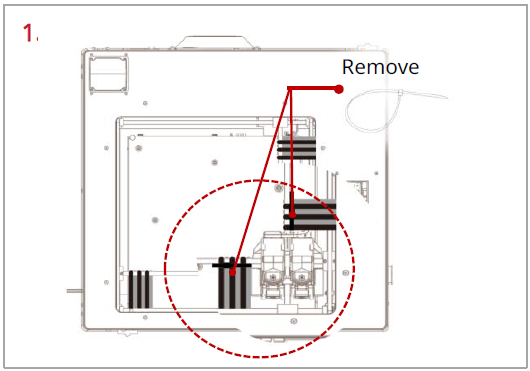
Remove, but do not cut, the four shipping zip ties for fixing the Z axes. Keep the shipping zip ties safe for further installation and subsequent transportation.
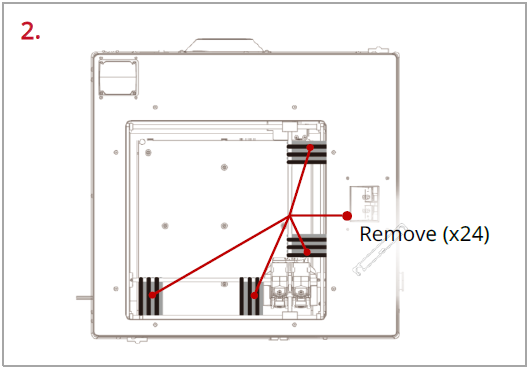
Before powering on the printer, make sure to peel off all the yellow stickers and remove the 24 security spacers. If the spacers are not removed, the spacers will damage the printer once the printer begins operating. Keep the security spacers carefully for further installation and subsequent transportation.
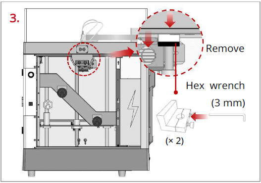
Remove the 4 screws on the screw clamps, using the included 3 mm hex wrench. The clamps are located on the top of the screw rods on the left and right sides of the printer. Keep the screw clamps and screws safe for further installation and subsequent transportation.
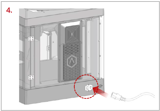
The printer contains a power cord that conforms to your current country (region). Connect it to the power inlet and outlet. Flip the switch of the printer.
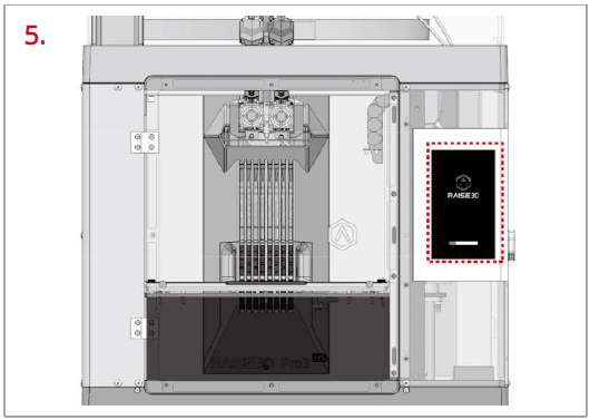
After the printer is powered on, the printer will enter the boot process. It takes about 60 seconds for the printer to enter the Start-up Wizard.
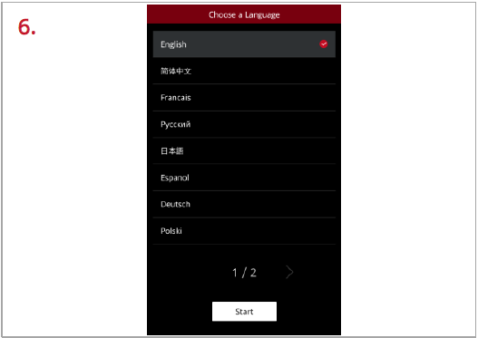
After the printer has entered the Start-up Wizard, you can follow the prompts on the screen for further operations, such as choosing the language for the printer.
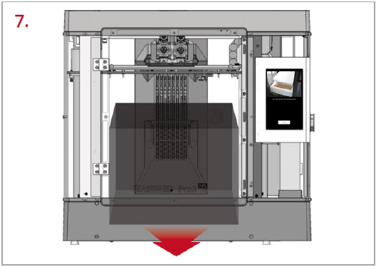
After confirming that all the safety spacers and screws are removed according to the screen prompts, tap “Next”. Open the front door, and take out the accessory box and filament box from the printer.
8. Keep following the Start-up Wizard to complete the basic settings, such as printer’s name, network, and RaiseCloud. After completing the basic settings, the printer will carry out the offset calibration (See chapter E for details).
E. Run the Offset Calibration
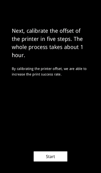
1. Offset calibration is to ensure that your printer will print successfully. There are 5 steps in the whole offset value calibration in the Start-up Wizard, and the whole process takes about 1 hour.
2. Please select an appropriate filament template, such as Raise3D Hyper Speed PLA, or you can add a new filament template. Raise3D Hyper Speed PLA filament is used for the calibration process in this tutorial.
Note:
1) It is recommended to use the same type of filaments for Offset Calibration. It is also recommended to use Raise3D Hyper Speed filaments.
2) When running the “R-Nozzle XY Offset” and “Dual Color Cube” in the Offset Calibration, PLA filaments must be used.
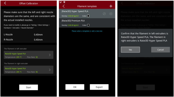
3. Run the 5-step Offset Calibration sequentially according to the prompts on the screen.
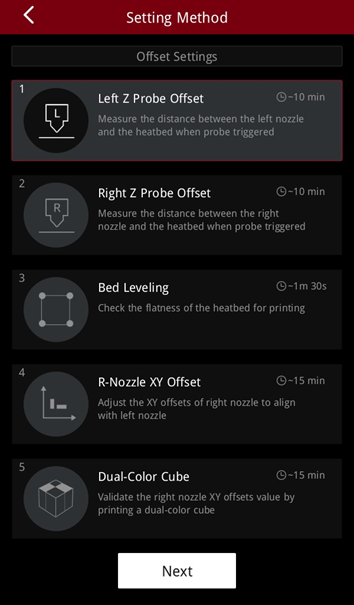
E.1 Run the Left Z Probe Offset
1. Enter the Left Z Probe Offset. Make sure that the nozzle and build plate are clean.
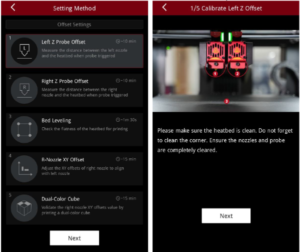
2. With a 0.3 mm feeler gauge, adjust the distance between the nozzle and the build plate as indicated by the prompts on the screen. Make sure that you can feel some resistance as the feeler gauge moves between the nozzle and build plate. Do not press hard on the build plate.
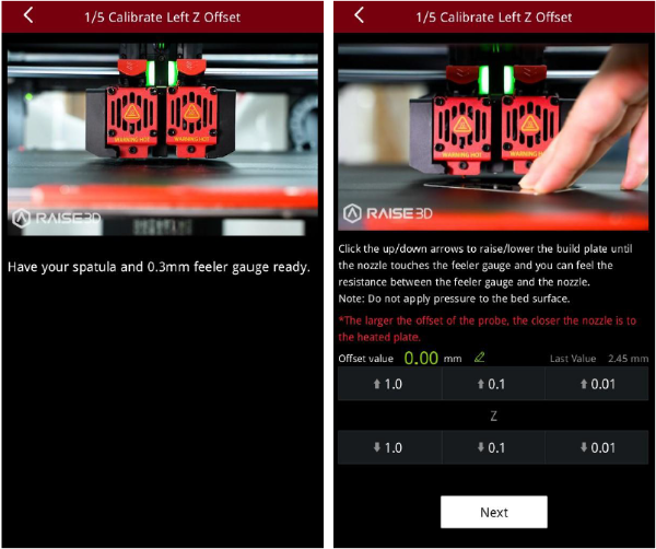
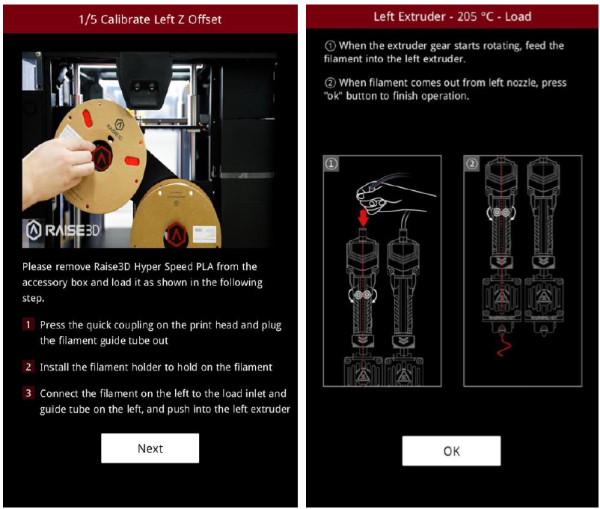
3. After adjusting the distance between the nozzle and the build plate, follow the prompt on the screen to install and load the filament.
Note: Two spools of Raise3D Hyper Speed PLA filament are used for calibration in this tutorial.
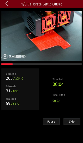
4. After loading the filament, the printer will start printing a 9-square calibration model. Wait for the model to finish printing.
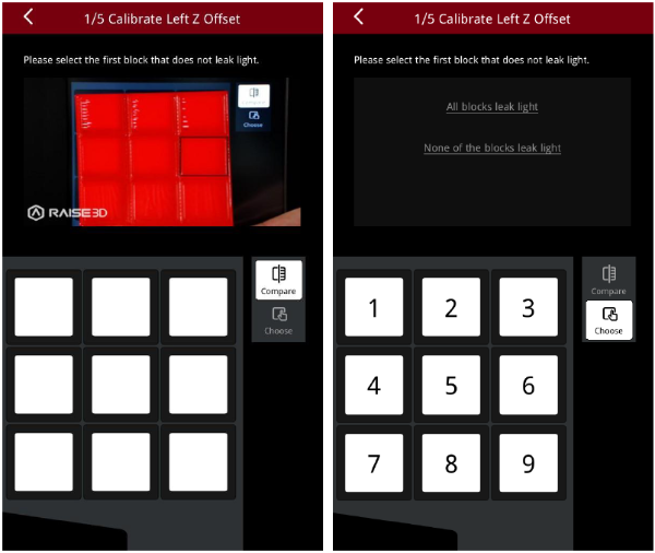
5. After the model is printed, compare the model with the on-screen example. Hold the model up against a light and select the first block that doesn’t leak light. The printer will automatically adjust the offset value of the left nozzle.
Note: If all the blocks leak light or do not leak light, it means that there may be deviations when measuring the distance between the build plate with a feeler gauge, and it is necessary to recalibrate by selecting the corresponding scenario.
●If all the blocks leak light, the distance between the nozzles and the build plate is too large. Select “All blocks leak light” and the machine will lower the nozzle and recalibrate.
●If all the blocks do not leak light, the distance between the nozzle and the build plate is too small. Select “None of the blocks leak light” and the machine will lift the nozzle and recalibrate.
E.2 Run the Right Z Probe Offset
1. Enter the Right Z Probe Offset. Make sure that the nozzle and build plate are clean.
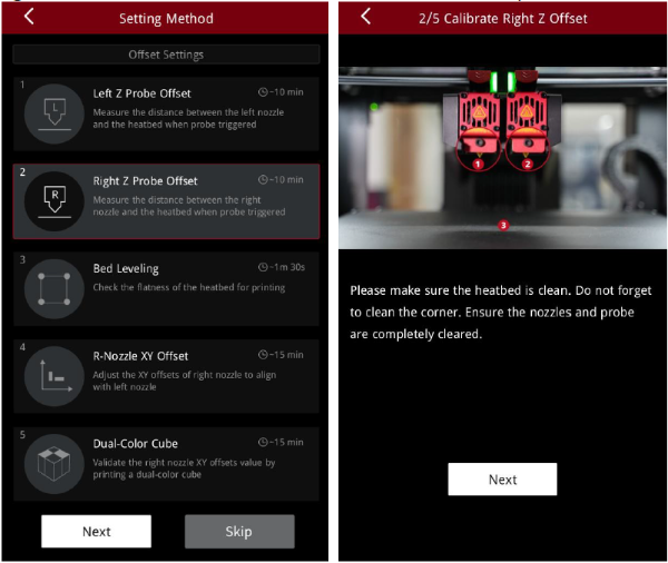
2. With a 0.3 mm feeler gauge, adjust the distance between the nozzle and the build plate according to the prompts on the screen. Make sure that you can feel some resistance as the feeler gauge moves between the nozzle and build plate. Do not press hard on the build plate.
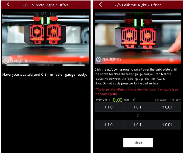
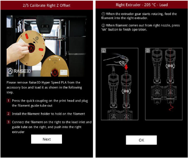
3. After adjusting the distance between the nozzle and the build plate, follow the prompt on the screen to install and load the filament.
Note: Two spools of Raise3D Hyper Speed PLA filament are used for calibration in this tutorial.
4. After loading the filament, the printer will start printing a 9-square calibration model. Wait for printing to complete.
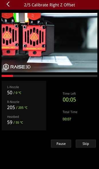
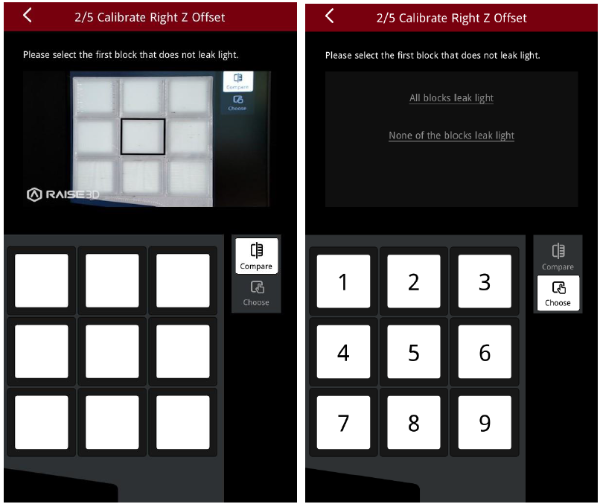
5. Dopo aver stampato il modello, confrontarlo con l’esempio sullo schermo. Tieni il modello contro una luce e seleziona il primo blocco che non perde luce. La stampante regolerà automaticamente il valore di offset dell’ugello destro.
Nota: se tutti i blocchi perdono luce o non perdono luce, significa che potrebbero esserci deviazioni durante la misurazione della distanza tra il piano di stampa con uno spessimetro ed è necessario ricalibrare selezionando lo scenario corrispondente.
●Se tutti i blocchi perdono luce, la distanza tra gli ugelli e il piano di stampa è troppo grande. Selezionare “Tutti i blocchi perdono luce” e la macchina abbasserà l’ugello e ricalibrerà.
●Se tutti i blocchi non perdono luce, la distanza tra l’ugello e il piano di stampa è troppo piccola. Selezionare “Nessuno dei blocchi perde luce” e la macchina solleverà l’ugello e si ricalibrerà.
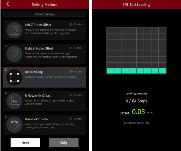
E.3 Livellamento del letto
1. Lo scopo di questo passaggio è calibrare la planarità del piano di stampa. La stampante rileverà automaticamente 64 punti sul piano di stampa e regolerà la planarità del piano di stampa.
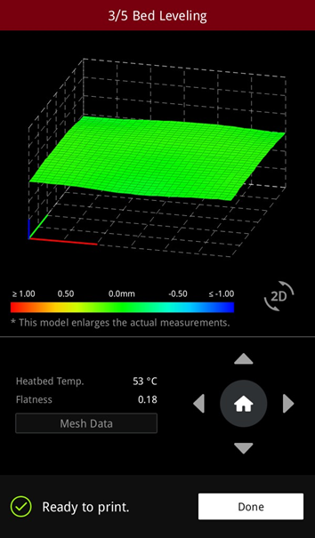
2. After the build plate is leveled, a visualized leveling result is displayed.
E.4 R-Nozzle XY Offset
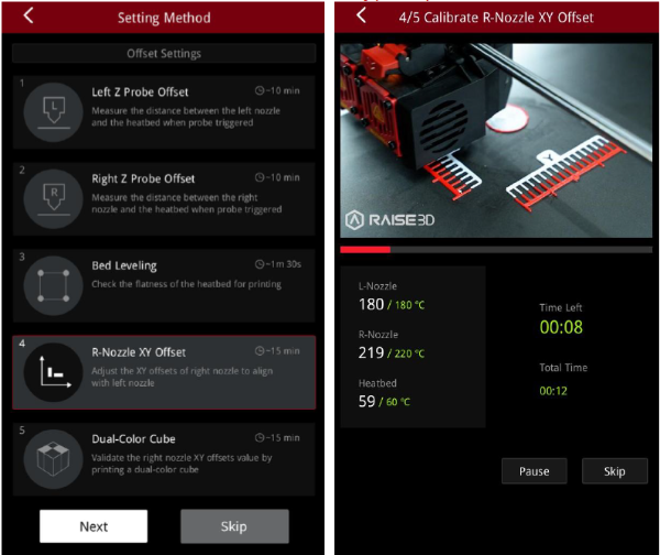
1. The purpose of this step is to calibrate the XY offset of the right nozzle so that it aligns with the left nozzle. The printer will heat up automatically and print two test models.
Note: This calibration can only be performed if both the left extruder and the right extruder are loaded with PLA filaments, otherwise this step cannot be performed. In this tutorial, the left and right extruders are loaded with Raise3D Hyper Speed PLA filaments.
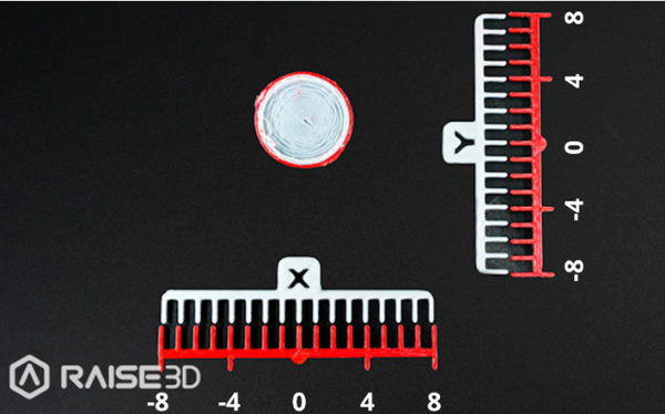
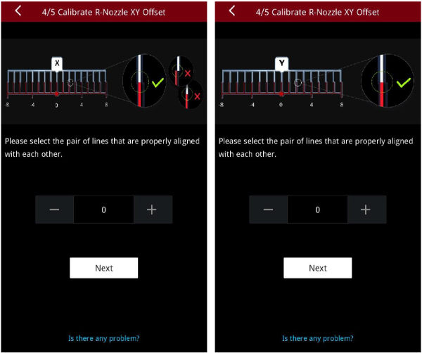
2. After printing, according to the instructions on the screen, select a pair of lines that are completely aligned on the X model and the Y model respectively. As exampled in the figure below, the corresponding number to the pair of aligned lines on the X model is 1, and the corresponding number to the pair of aligned lines on the Y model is 2.
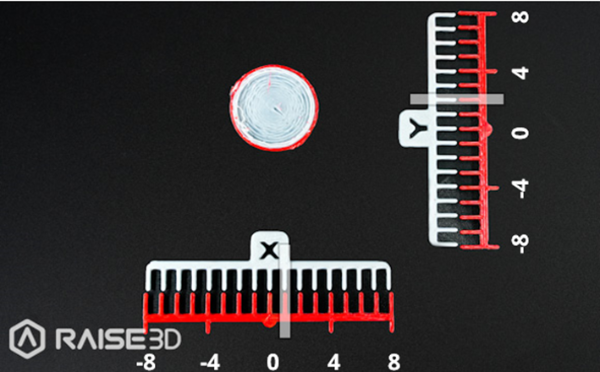
3. Input the serial number on the screen. The printer will automatically calibrate the XY Offset of the right nozzle.
E.5 Dual-Color Cube
1. This step aims to validate the XY offset value of the right nozzle by printing dual-color cubes.
Note: This calibration can only be performed if both the left extruder and the right extruder are loaded with PLA filaments, otherwise this step cannot be performed. In this tutorial, the left and right extruders are loaded with Raise3D Hyper Speed PLA filaments.
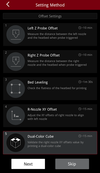
2. After printing, please compare the printed dual-color cube with the sample graphic on the screen, and check whether there is an obvious gap between the color blocks.
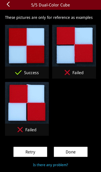
3. If there is no gap between the color blocks, it means that the XYZ direction offset value of the right nozzle is within a reasonable range. Please tap “Done” to complete the 5-step Offset Calibration.
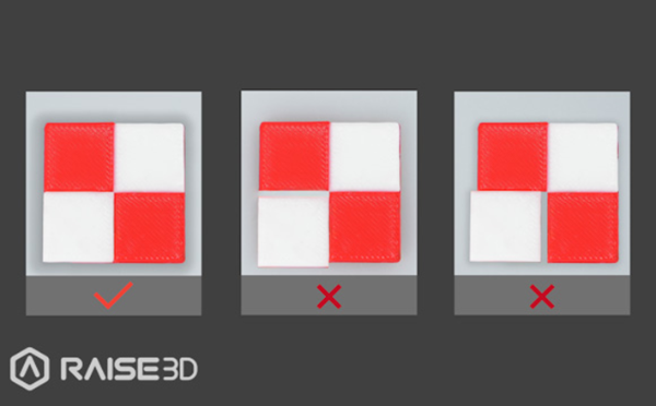
4. If there is a gap between the color blocks, please tap “Retry” and re-run the 4th and 5th steps of the 5-step Offset Calibration to recalibrate the XY offset value of the right nozzle.
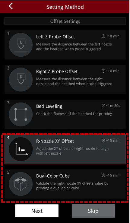
E.6 Calibration Finished
After the 5-step calibration is completed, you can start your first high-speed print!
F. ideaMaker Installation

1.Download the latest version from: https://www.raise3d.com/download/.
2.Open the installer and select the installation language. Select the appropriate ideaMaker install location and click “Next”.
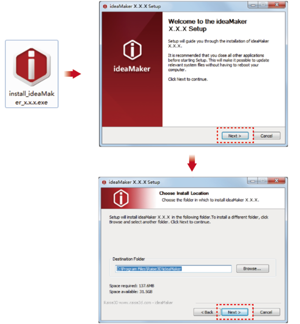
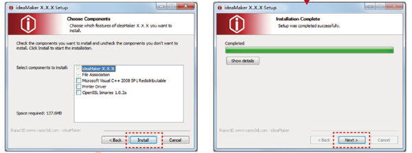
3.Follow the instructions provided by the guide and click “Install”. After the installation is complete, click “Next” to go to the next step.
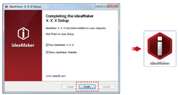
4.Click “Finish” and ideaMaker is installed.

1.Download the latest version from: https://www.raise3d.com/download/.
2.Drag the ideaMaker icon (left) into the Application folder on the right side.
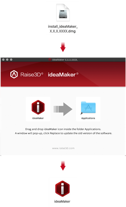
G. Slice Model
1. After downloading and installing ideaMaker onto your computer, import a model into ideaMaker.

2. Select the appropriate Raise3D Pro3 HS or Pro3 Plus HS printer. Select extruder filament templates.
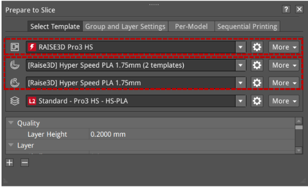
3. Select a desired slicing template for the filament.
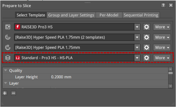
1) The templates will be marked L1/L2 according to their values of velocity, acceleration, and volumetric flow rate within their settings.
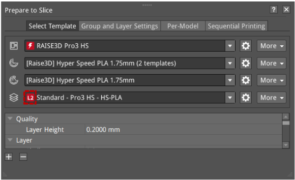
2) ideaMaker will judge all parameters related to speed, acceleration, and flow rate in the current template settings. As long as one parameter value reaches L1 or L2, after the template is saved, it will add L1 or L2 labels to the template (L0 will not be displayed).
| Parameter | Nozzle | Speed Range | |||
| Acceleration(mm/s2) | 0.6 mm | x <= 1500 | 1500 < x <= 5000 | 5000 < x <= 10000 | x > 10000 |
| 0.4 mm | |||||
| Speed(mm/s) | 0.6 mm | x <= 100 | 100 < x <= 150 | 150 < x <= 350 | x > 350 |
| 0.4 mm | |||||
| Volumetric Flow Rate(mm3/s) | 0.6 mm | x <= 10 | 10 < x <= 25 | 25 < x <= 40 | x > 40 |
| 0.4 mm | 10 < x <= 15 | 15 < x <= 30 | x > 30 | ||
| Label Display | L0(no display) | L1 | L2 | L0(no display) | |
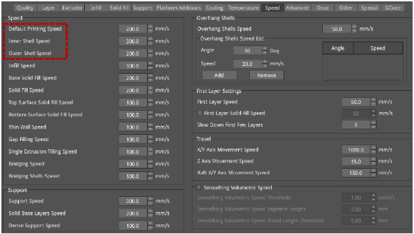
The speed judgment includes Default Printing Speed, Inner Shell Speed, and Outer Shell Speed. Click the “Edit ” icon to enter the advanced settings of the template. The speed judgment items are shown in the red box below.
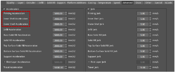
Acceleration judgment includes Printing Acceleration, Inner Shell Acceleration, and Outer Shell Acceleration, as shown in the red box below.
Volumetric flow rate calculation formula: Volumetric Speed = Layer Height * Extrusion Width * Speed
The volumetric flow rate is determined by the Layer Height, Extrusion Width, and Speed.
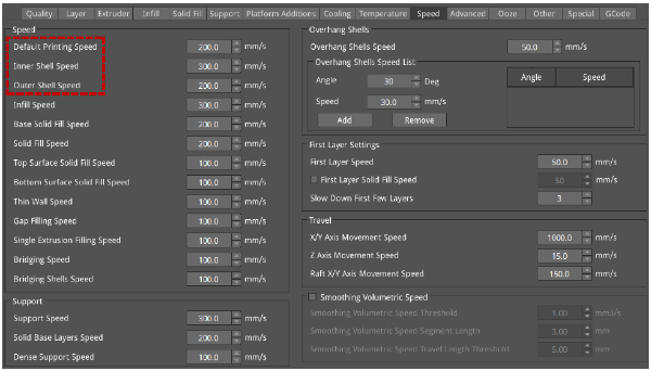
Volumetric flow rate judgment includes Default Printing Speed, Inner Shell Speed, and Outer Shell Speed, as shown in the red box below.


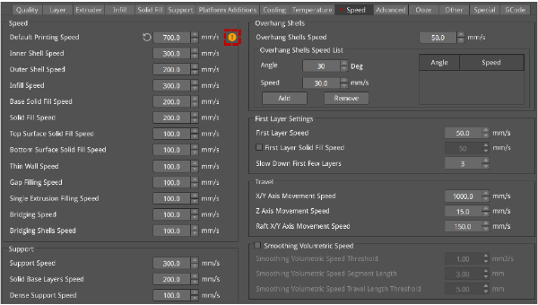
3) In ideaMaker, Raise3D filaments have threshold limits for speed, acceleration, and volumetric flow rate in Standard Mode and Hyper Speed Modes respectively, and if each speed exceeds the threshold, ideaMaker will display an alert.
When the speed, acceleration, and volumetric flow rate exceed the threshold, a yellow exclamation mark reminder is given, and an explanation is given when the mouse hovers over it.
4. After reviewing the parameters, click “Start Slicing” to slice the model.

5. After slicing, you can export the file to the local disk and then upload it to the printer, or you can upload it directly to the Pro3 HS series printer to start your Hyper Speed printing.

H. Dual Extruder Printing
H.1 Load Filament
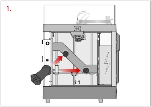
Open the side door of the printer. Place two filament holders on the installation points.
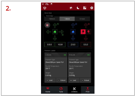
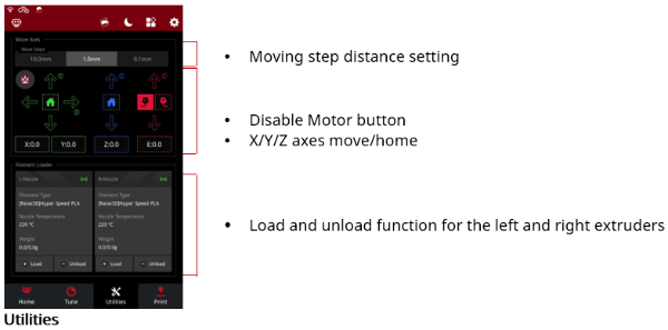
Select the “Utilities” tab at the bottom of the screen. Tap “Load” for the left or right nozzle.
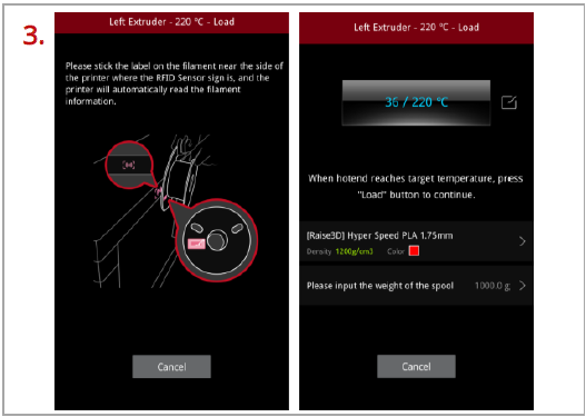
Following the prompts on the screen, take out a roll of Raise3D Hyper Speed PLA. Attach the tag on the filament to the RFID sensor above the holders, and the printer will automatically read the filament information.
Important: These instructions are based on the properties of Raise3D Hyper Speed PLA filament. The Pro3 HS series printers come with two spools of Raise3D Hyper Speed PLA. We recommend using Raise3D Hyper Speed PLA for testing and initial setup.
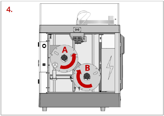
Install the filament on the holder.
Note: As shown in the left figure, if the filament is installed at the point A, it is recommended to place the filament in a clockwise direction; if the filament spool installed at the point B, it is recommended to place the filament spool in a counterclockwise direction.
Placing the filaments in the suggested directions, as shown in the figure, can make feeding filaments smoother.
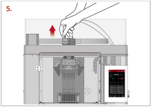
Press and hold the metal quick connector on the extruder and pull out the filament guide tube.
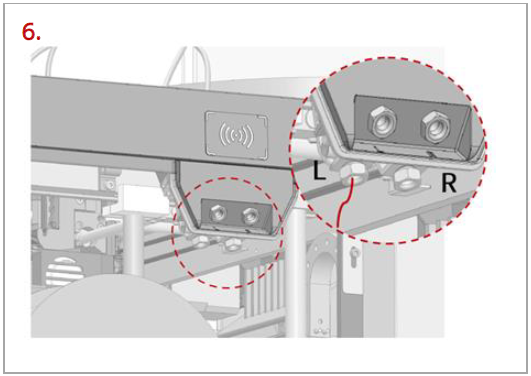
Find the tip of the filament. Pass the filament into the left or right inlet until the tip of the filament is completely through the guide tube.
Note: Here we take the left extruder as an example, because the operation of the left extruder is the same as that of the right extruder. The left and right inlets are as shown in the figure, please do not mix them up.
You can also feed the filament from an external filament box through the external left/right inlets located on the right side.
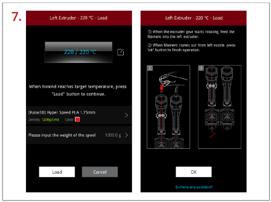
When the printer reaches the target temperature, tap “Load”. The extruder gear will start to rotate. Gently push the filament into the extruder. When the filament is extruded out from the nozzle, tap “OK” to complete the loading. Insert the guide tube back into the quick connector.
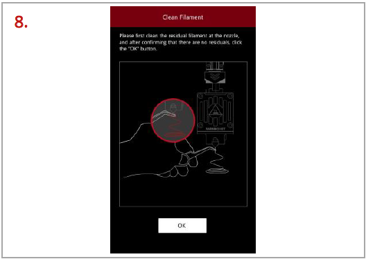
Clean the residual filament at the nozzle. Tap “OK” and loading filament is complete.
H.2 Start Printing
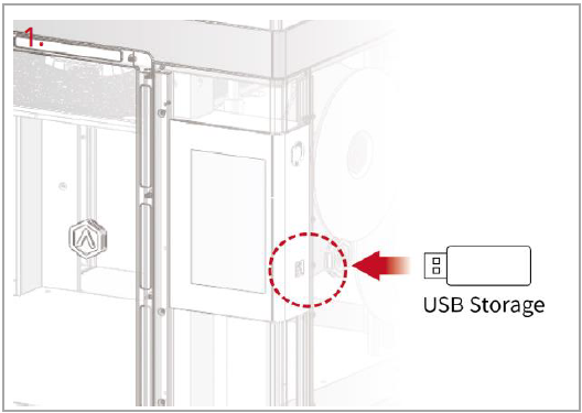
Insert the USB device that contains your sliced model files (.gcode or .data) into the USB port on the side of the touch screen.
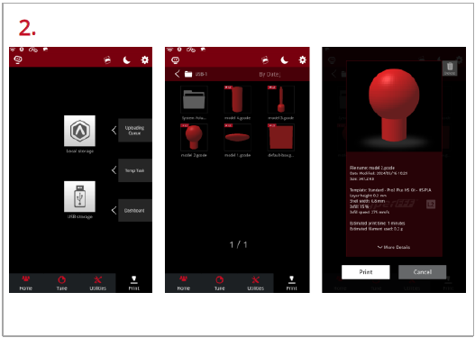
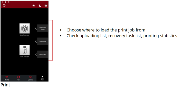
Select the “Print” tab at the bottom of the touch screen and choose “USB Storage” to open the file storage path. Select your sliced model file to check the printing parameters and settings. Tap “Print” to start printing the model.
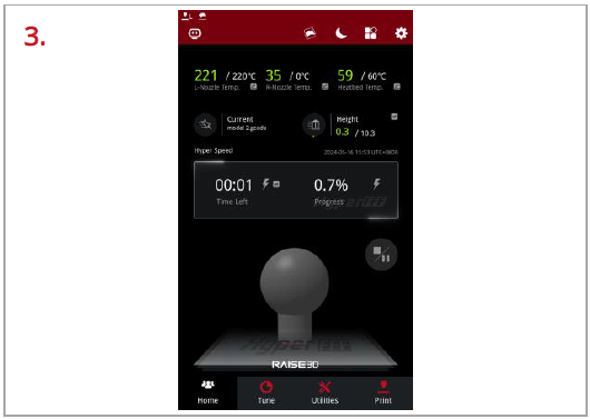
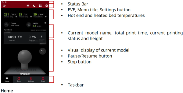
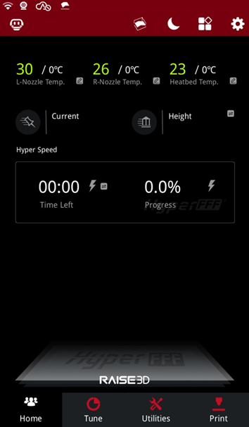
During the printing process, you can check the printing status from the “Home” interface on the touch screen, including the remaining printing time and other parameters.
Note: The model image will only be displayed on the touch screen when the file is sliced by ideaMaker, and the .data file is exported to the USB drive or the .data file is uploaded to the printer.
I. Remove the Printed Model
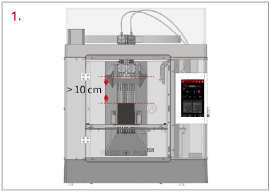
Make sure the printer is idle, and there is at least a 10 cm gap between the printed model’s top and the nozzle. This is to prevent the nozzle from scratching the model or damaging the model when it is taken out.
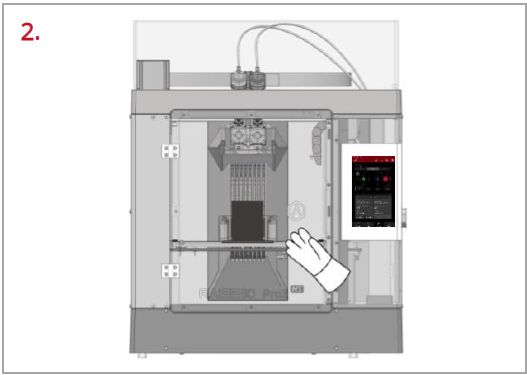
Wait for the build plate and nozzles to cool down to room temperature before removing any models. If you want to remove the model before they have sufficiently cooled down, please wear the heat-resistant gloves from the attached accessory box.
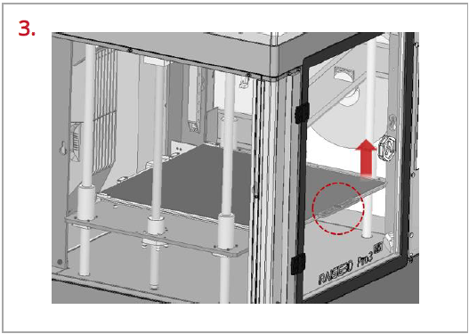
Hold the red protective handle (as shown in the red circle) to gently lift the printing surface, and then take out the printing surface from the printer.
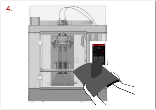
Bend the printing surface repeatedly along the longer span of the model until the model is detached from the printing surface.
Note: Do not directly touch the edge of the printing surface to avoid injury. Do not over-bend the printing surface to avoid damaging the plate or causing the plate to bounce off from hands.
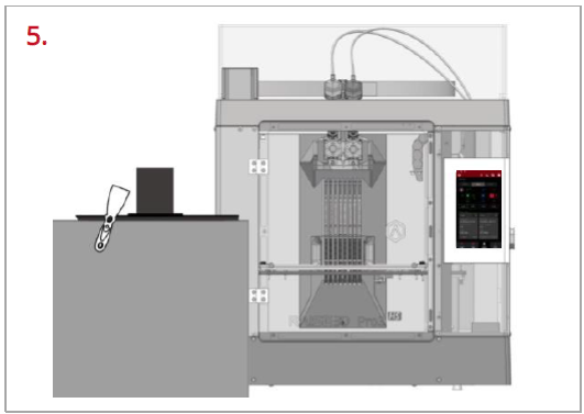
If the model is not entirely loose or if you feel the model is hard to remove after bending the printing surface several times, use the spatula from the attached accessory box to remove it.
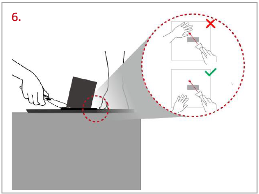
Use one hand to hold the printing surface and use the other hand to scrape off the model with the spatula.
Note: We recommend placing the spatula above the plate and inserting it into the gap between the model and the plate. If the model is printed with the Raft, it is better to scrape the prints along the infill direction of the Raft. Do not put your hands in front of the spatula to prevent injury.
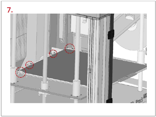
After the model is removed, the printing surface needs to be reinstalled onto the build plate. Gently put the printing surface to its original position by holding the red protective handle. Place the printing surface against the four side strips (as shown in the red circles), and then attach the entire printing surface to the build plate.
J. User Interface
